Recommended Ultrasound Terminology
B
B/A
A measure of the nonlinearity of a material. It is defined as the ratio of the values of A and B, the coefficients of the first and second terms of the Taylor series expansion of the equation relating the acoustic pressure exerted on a material to its density. The equation defining A and B is:pressure = A (relative change in density) + (B/2)(relative change in density)2
Related terms: coefficient of nonlinearity, acoustic impedance, speed of sound
back end
Term used to describe the part of a conventional ultrasound imaging system involved with the signal processing and display of beamformed ultrasound signals. In systems with software beamforming, the beamforming and display functions may be interrelated.
background noise
The unwanted residual signal that is present whether the sound source of interest is in operation.
backing layer
Absorbing material at the back of the active transducer material that enhances the response of the transducer. This material attenuates ultrasound going in the opposite of the intended direction for propagation and reflects ultrasound into the preferred direction. It broadens the bandwidth and shortens the time response of the transducer (see Figure 20).
_page_21.png?sfvrsn=fb3ceba8_4)
Related terms: damping (transducer), matching layer
backscatter
The scattered sound that travels back toward the source transducer. When used as a verb, backscatter means to scatter a traveling sound wave in a direction generally opposite to that of the incident wave.
backscatter coefficient
The acoustic power scattered in a direction opposite to that of the incident beam per unit volume of material, per steradian, per unit incident beam intensity.
backscatter contrast
Related term: contrast (object)
backscattered energy
The portion of the incident acoustic energy scattered back toward the source.
band sound pressure level
The level of the sound pressure produced within a specified frequency band. Note: The band may be specified by its lower and upper cutoff frequencies or by its geometric center frequency and bandwidth. The width of the band may be indicated by a modifier such as one octave band (sound pressure) level, one-half octave band level, or one- third octave band level.
bandpass filter
A device that has a limited bandwidth. Bandpass filters are sometimes used in the receiver of an ultrasound scanner to filter away signals outside the frequency band of desired signals from the transducer. Piezoelectric transducers may also be considered bandpass filters in that when shock is excited by a wideband pulse, they produce pulses containing a relatively narrow band of frequencies.
bandwidth
A measure of the range of frequencies that a device is capable of transmitting or receiving (colloquial). Difference in the frequencies ƒ1 and ƒ2 at which the amplitude of the spectrum of the acoustic pressure first becomes 3 dB lower than the peak amplitude. Bandwidth is usually specified in megahertz (MHz).
Related term: center frequency
barium titanate (BaTiO3)
A material belonging to a class of ferroelectric ceramics from which piezoelectric transducers are often fabricated.
Barker code
A family of unique binary sequences of N values of –1 and +1, satisfying the condition that all sums of the products of the terms taken 2 at a time never exceed 1. Barker codes are useful in producing coded pulse trains.
Related term: coded excitation
baseline shift (zero shift)
A control that allows the axis representing the Doppler shift frequency on the spectral display to be allocated entirely to forward flow, reverse flow, or a mixture of the two. The effect is to “shift” the zero frequency axis up or down. This procedure is useful when aliasing is present in a signal representing unidirectional flow. It does not affect the Nyquist limit.
basket pattern
Color Doppler and contrast-enhanced ultrasound pattern of macrovascularization consisting of a vascular ring that circumscribes the lesion starting from a pole and then gives discrete, irregular branches intralesionally. A common feature of hepatocellular carcinoma.
beam
The directed acoustic emission produced by a transducer (see Figures 4 and 10).
_page_05.png?sfvrsn=a7f3c04f_3)
_page_11.png?sfvrsn=6387ddb_4)
Related term: beam pattern
beam alignment axis
See beam axis.
beam area
The cross-sectional area of an ultrasound beam (colloquial). For measurement purposes, beam area is the area bounded by the –6-dB pulse-pressure-squared integral contour in a specified plane perpendicular to the beam axis. It can be estimated by πab/4, where a and b are the –6-dB beamwidths along the azimuth and elevation axes.
Related terms: azimuth plane, beam, beam pattern, beamwidth, elevation plane
beam-average pulse acoustic pressure
The pulse acoustic pressure from one ultrasonic transducer or ultrasonic transducer element group averaged over the –6-dB beam area in a specified plane or in a plane containing the spatial-peak temporal-peak acoustic pressure for that particular ultrasonic transducer or ultrasonic transducer element group. The unit is pascal (Pa). Note: A –6-dB beam area is commonly used; however, other beam areas may be used.
Related terms: beam area, temporal-peak acoustic pressure, ultrasonic transducer, ultrasonic transducer element group
beam-average pulse-average intensity
The pulse-average intensity from one ultrasonic transducer or ultrasonic transducer element group averaged over the –6-dB beam-area in a specified plane or in a plane containing the spatial-peak temporal-peak acoustic pressure for that particular ultrasonic transducer or ultrasonic transducer element group. The unit is watt per square meter (W/m2). Note: A –6-dB beam area is commonly used; however, other beam areas may be used.
Related terms: beam area, intensity, ultrasonic transducer, ultrasonic transducer element group
beam-average root mean square acoustic pressure
The root mean square acoustic pressure from one ultrasonic transducer or ultrasonic transducer element group averaged over the –6-dB beam area in a specified plane or in a plane containing the spatial-peak temporal-peak acoustic pressure for that particular ultrasonic transducer or ultrasonic transducer element group. The unit is pascal (Pa). Note: A –6-dB beam area is commonly used; however, other beam areas may be used.
beam-average temporal-average intensity
The temporal-average intensity from one ultrasonic transducer or ultrasonic transducer element group averaged over the –6-dB beam area in a specified plane or in a plane containing the spatial-peak temporal-peak acoustic pressure for that particular ultrasonic transducer or ultrasonic transducer element group. The unit is watt per square meter (W/m2). Note: A –6-dB beam area is commonly used; however, other beam areas may be used.
Related term: intensity
beam axis
A convenient indicator of the direction of a sound beam. The beam axis is located at the center of an ultrasound beam and lies along the direction of sound propagation (see Figures 2, 3, 5, 7, 9, and 27).
_page_03.png?sfvrsn=3bd1f8cd_3)
_page_04.png?sfvrsn=74577a7b_3)
_page_06.png?sfvrsn=a149f63_3)
_page_08.png?sfvrsn=546d2f96_4)
_page_10.png?sfvrsn=19f41c0d_4)
_page_28.png?sfvrsn=b40dff6d_3)
beam center
A point in a scan plane, usually perpendicular to the beam alignment axis, at which the spatial-peak temporal-peak acoustic intensity occurs.
Related term: beam axis
beam cross-sectional area
Transmitted beam cross-sectional area is the area on the surface of a plane perpendicular to the beam axis consisting of all points where the acoustic pressure is greater than 50% of the maximum acoustic pressure in that plane. Also used less often to describe an area in reflection as the area of that portion of a surface, in a plane perpendicular to the beam axis, that is bounded by that contour of the pulse-echo amplitude from a specified point or line reflector that exceeds a specified percentage of the maximum, eg, 25% (–12 dB), transducer signal in that plane.
beam cross-sectional profile
See beam profile.
beam divergence
The widening of the beam as it travels away from the transducer.
beamformer
A beamformer is a method of adjusting, combining, or processing waveforms going into or received from an array of transducer elements to shape and direct an ultrasound beam. (see Figures 10, 29, 30 and 35)
See array, beam pattern, directivity function, delay and sum beamformer, receive beamformer, and transmit beamformer.
beamforming
The process whereby the beamformer and/or mechanical lenses, concave transducer elements, or mirrors determine the complete transmit or receive beam pattern.
beam-minimum
The location along the beam axis in a specified longitudinal plane where the field of a nonfocusing ultrasonic transducer has minimum –6-dB beamwidth (see Figures 3 and 7). Under ideal conditions, this location corresponds to the transition distance for circularly symmetric fields and close to the transition distance for other geometries. For an example of minimum beamwidth when the specified longitudinal plane is the elevation plane, see Figure 33.
_page_34.png?sfvrsn=8a2adaf6_3)
Related terms: beam-minimum depth, transition distance
beam-minimum depth
The distance from the beam-minimum to the transducer aperture plane, or in the case of measurement, the source aperture plane (see Figures 3 and 7).
Related terms: beam-minimum, source aperture plane, transducer aperture plane
beam pattern
A description, often presented graphically, of the response of the transducer as a function of the angle with respect to the direction of the transmitted or incident sound waves in a specified plane and at a specified frequency. A complete description of the beam pattern of a transducer would require a 3-dimensional presentation. The beam pattern is often shown as the response relative to the maximum response. Note that the beam pattern for a transducer may be different for transmit and receive modes (see Figures 4, 14, and 10).
_page_15.png?sfvrsn=76ab9215_4)
beam plot
A graphic representation of a beam profile (see Figure 14).
Related term: beam pattern
beam profile
The sound pressure amplitude distribution along a line perpendicular to the beam axis (see Figures 14 and 25).
Related terms: pulse-echo response profile, beam pattern
beam-to-vessel angle
The angle between the axis of the ultrasound beam and the axis of a vessel lumen. This will only be equal to the Doppler angle when flow is parallel to the vessel axis.
Related terms: beam, Doppler angle
beam uniformity ratio
The ratio of the spatial-peak temporal-average intensity (ISPTA) to the spatial-average temporal-average intensity (ISATA) where both quantities are measured in a plane perpendicular to the beam axis.
Related terms: beam axis, intensity
beamformer
A beamformer is a method of adjusting, combining, or processing waveforms going into or received from an array of transducer elements to produce an ultrasound beam.
See delay and sum beamformer, receive beamformer, and transmit beamformer.
beamwidth (transmission)
The maximum transverse distance between points on the beam profile at a given depth where the acoustic pressure is a specified fraction of the maximum acoustic pressure in the profile. This may also be expressed as the angle formed between lines from the location of these two points to the point of intersection of the beam axis and the surface of the transducer assembly (see Figure 14).
beamwidth cylindrical focus
For nonaxisymmetric fields, the point on the beam axis for which the –6-dB beamwidth perpendicular to the axis in a given longitudinal plane is a minimum. When cylindrical focusing has been used, this position will, in general, be different for different longitudinal planes.
Related terms: beam axis, beamwidth, cylindrical wave, focusing, longitudinal plane
beamwidth focal line
The line perpendicular to the beam axis in a given longitudinal plane that passes through the cylindrical beamwidth focus for that longitudinal plane.
Related terms: beam axis, beamwidth, cylindrical wave, focusing, longitudinal plane
beamwidth focal plane
The plane perpendicular to the beam axis that contains the spherical beam focus.
Related terms: beam axis, focus, spherical wave
beamwidth spherical focus
The point along the beam axis for which the –6-dB beam area perpendicular to the axis is a minimum.
Related terms: beam axis, focus, spherical wave
beat
The periodic variation in the amplitude of a wave that is the superposition of two simple harmonic waves of different frequencies.
bel
The logarithm to the base 10 of the ratio of two powers or intensities.
Related term: decibel
Bernoulli effect
The reduction in pressure that accompanies an increase in the velocity of fluid flow.
Bernoulli equation
The equation that states that the total fluid energy per unit volume along a streamline of fluid flow is constant. This is a form of the more general law of conservation of energy.
Bessel beam
bioeffect
A change in the structure or function of a biological structure, ie, a biological effect.
bioeffect (ultrasound induced)
A change in a biological structure caused by ultrasound.
Related term: intensity
bit
A contraction of “binary digit.” A bit can assume one of two possible values usually represented by 0 and 1.
blood pool contrast media
Those contrast agents that remain intravascular and do not spread to the interstitium. Blood pool agents act as flow tracers.
B-mode (brightness modulated)
A method of image display in which the amplitude envelope of the echo signal is represented by modulation of the brightness of the corresponding image point. The position of the echo, displayed in the scan plane, is determined from the position and angulation of the beam and the transit time of the acoustic pulse (see Figures 29 and 30).
_page_30.png?sfvrsn=92a82fb8_3)
_page_31.png?sfvrsn=c358aa75_3)
Related terms: pulse echo, scan plane, B-scan
bone conduction
The transmission of sound to the internal ear mediated by mechanical vibration of the cranial bones and soft tissues.
bone thermal index (TIB)
The thermal index developed for ultrasound exposures that include bone positioned deep within the body, such as the fetal skull but not the postnatal or adult skull.
Related terms: cranial thermal index (TIC), soft issue thermal index (TIS), thermal index
boundary conditions
The geometric conditions that must be satisfied at boundaries when a solution to a problem is applied in a specific application or instance.
boundary layer
The thin layer of quasistationary fluid in contact with the walls of the containing vessel.
Bragg diffraction
In acoustics, the process of scattering from an array of scatterers such that, through constructive and destructive interference, there results more sound energy in some directions and less in others.
brightness-modulated display
See B-mode.
brightness modulation
An echo display technique in which the brightness of a displayed echo varies with the echo amplitude.
Related term: B-mode
broadband signal
A signal containing a wide range of frequencies (colloquial). A broadband signal is one for which the product of the pulse duration and the effective frequency is less than 2.
Related terms: Contrast with narrow bandwidth, wideband
bruit
The name given to sounds sometimes associated with disturbed and turbulent flow. They arise from the periodic variation in shear stress on the vessel wall, which causes it to vibrate.
Burgers model
A complex model of a viscoelastic material represented by a series connection of a Maxwell model and a Voigt model as shown in the diagram below. This model contains two dashpots and two purely elastic springs.
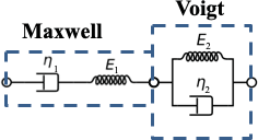
Related terms: dashpot, elastic spring, Maxwell model, Kelvin model, Kelvin-Voigt model, standard linear viscoelastic model, Voigt model
B-scan
A scanning procedure in which echo information is displayed in the B-mode.
Related term: B-mode
B-scan image
A sonogram produced by a B-scan procedure. Alternatively, a B-mode image.
bubble
A cavity that is nearly or completely surrounded by a different material, usually liquid.
bubble, encapsulated
A bubble in which the gas and liquid phases are separated by a thin shell of insoluble or liquid material.
bubble noise artifact (spectral)
Spectral Doppler artifact due to the presence of contrast medium microbubbles within the sampled volume. Sharp, needle-shaped signals of high amplitude appear on the Doppler spectrum, and a crackling noise is heard in the audio. Spectral Doppler analysis should be performed before contrast medium injection. Otherwise, it may be necessary to decrease Doppler gain and to increase Doppler signal filtering. Further research is needed to determine the effects of sonographic contrast media on spectral waveforms.
Related terms: Doppler spectrum, microbubble, waveform
bulk elastic modulus
See bulk modulus.
bulk modulus
A measure of stiffness. The ratio of the change in pressure to the resulting fractional reduction in volume. This equals the reciprocal of compressibility: B = –dp/(dV/V0), where B is bulk modulus, dp is the increase in pressure, and dV/V0 is the fractional increase in volume.
Related terms: compressibility, stiffness